| AutoCAD and SDS/2 Tips, by Alex Borodulin |
Contents:
Get rid from duplicates (AutoCAD and SDS/2)
Join Polylines (AutoCAD and SDS/2)
Try to apply AutoCAD ‘qleader’ command differently. Use the following sequence of prompts:
Instead of specifying next (3rd) point just press ‘Enter’ or space bar on the keyboard and then type text or click ‘Enter’ to get Mtext window.
If you would use this method, the Mtext will always follow the leader. Move (mirror) text attached to the leader using grips or regular selection - and location (direction) of the leader will be changed respectively.
In my drafting practice instead of ‘qleader’ command I’m using LISP routine for adding leaders:
(DEFUN
C:LL()(COMMAND "LEADER" PAUSE PAUSE "A" "" "M" ""))
To use this routine, you should have dimension style containing separate assignment for leader (text vertical position: CENTERED). The advantage of my setting (dimension style): I don’t need to make settings of ‘qleader’ at all and the command is faster (very quick leader?). I always have leader attached to the middle of Mtext and never annoying prompt for width of text as with ‘qleader’.
How flexible are Very Quick Leaders for modifications you can see by playing movie:
Often you need to transfer Paper Space objects to Model Space and visa versa. In Express tools menu you can find ‘Layout tools’ menu item. Click on ‘Change Space ms/ps’ to perform transferring objects

command. Before using this command (try also others in ‘Layout tools’, they are worth for applying!) I would recommend you to read Express tools help file.
‘Change Space ms/ps’ command is a real time saving procedure. You can perform fast navigation (no regeneration of the screen is involved).
|
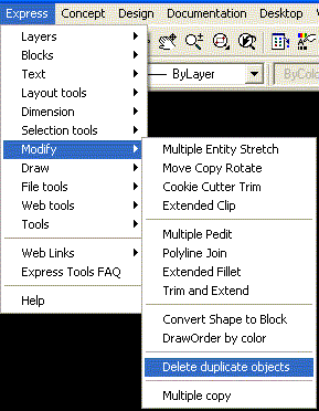
When you generate erection view in SDS/2, especially with selected 'Wire' option (steel 3D option), you can get huge size of DXF file: 10 or even 15 MB. If you are planning to use DXF file for modifications in AutoCAD, you can significantly reduce the size of file by using 'Delete duplicate objects' command from 'Express' tool menu. Unfortunately I did not find this command in AutoCAD 2004 'Express' tools. |
 |
Views in model space also can save your time while editing of drawings. Switching between views is faster than performing ‘Zoom All’ with the following ‘Zoom Window’ command. The only problem: standard way to call out the ‘View’ command (with dialog window) is too long. You can do it faster. Zoom in to select area you are suppose to use as a view.
Type: -v at the command prompt
Type: S to save view
Type: 1 to give a name for view (any name is acceptable, just make it easy)
Press ‘Enter’
Now you can work on your drawing and if you wish to restore saved view 1 you do:
Type: -v at the command prompt
Type: R
Type: 1
Press ‘Enter’
Look at the picture below.
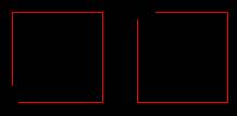
We have 2 contours (could be 60 or 260). We need to apply hatch for all of them. Due to contours are not closed, we have to work individually with each of them to make closed boundary. Tedious, isn’t it?
Solution: use ‘PEdit’ command with ‘Multiple option’. Read the following lines of command prompts with comments:
|
Command Prompts |
Comments |
|
Command: PEDIT |
|
|
Select polyline or [Multiple]: M |
|
|
Select objects: Specify opposite corner: 8 found Select objects: |
Select lines (polylines) on screen |
|
Convert Lines and Arcs to polylines [Yes/No]? <Y> Y |
|
|
Enter an option [Close/Open/Join/Width/Fit/Spline/Decurve/Ltype gen/Undo]: J Join Type = Extend |
|
|
Enter fuzz distance or [Jointype] <0.0500>: 0.06 |
Fuzz is a gap between ends of lines. In this example biggest value of fuzz is 0.05. The value 0.06 was chosen |
|
6 segments added to 2 polylines |
|
Try this sequence of commands. Next picture represents result:
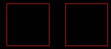
This tip can help SDS/2 users in editing of DXF drawings transferred to AutoCAD: join segment of holes (get one polyline instead of 18 segments), leaders and contours of members.
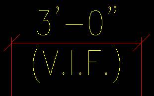
To create dimension with addition line of text below dimension line, use ‘DDedit’ command. In Mtext editor window add at the end the contents of bottom line with prefix \X. Example:
|
Dimension |
Mtext editor |
|
|
|
There is no need to have dozens of dimensions styles in system. One style can work. Change ‘Dimscale’ variable, make it equal 24 and you are ready to work in scale ½” = 1’-0”. Or make ‘Dimscale’ equal 96 and you are ready to work in scale 1/8” = 1’-0”.
Call out ‘Trim’ command. Select objects. Next press ‘Enter’ instead of selecting cutting edges (prompt from AutoCAD:
Select object to trim or shift-select to extend or [Project/Edge/Undo]:)
Now you can trim or extend (by holding Shift on keyboard) selected objects.
How do you change names of layers, blocks etc. in AutoCAD dialog windows or files’ (folders’) names in Windows Explorer? Click on Item, right click of mouse and select from contents menu: Rename.
There is an alternative way for renaming: click on item (layer name or file or folder), next press <F2> on keyboard and type new name. I found this way is more convenient.
Alex Borodulin